Geometric DFMPro 9.0.0.2301 for NXSeries
- 30.12.2021
- 89
Geometric DFMPro 9.0.0.2301 for NXSeries | 287.5 mb
Geometric Ltd. a leader in Product lifecycle Management (PLM), Global Engineering Services and Offshore Product Development (OPD) Solutions and Technologies, announced the release of version 9.0 of its automated design for manufacturability solution, DFMPro for NX software.
NX 2007 Series Support
Added New Rules
Composite Module
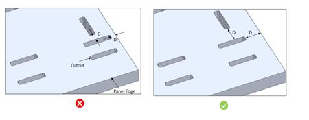
Minimum Distance Between Pocket to Panel Edge
Composite structure panels used in aerospace products have a higher strength-to-weight ratio. The minimum distance between cutouts, pockets, and panel edges should be maintained to avoid tearing composite panels. It could affect the load-carrying capacity of the panel and may result in damage during loading conditions. Maintaining a sufficient distance between the cutouts, pockets, and panel edges are always recommended
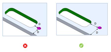
Minimum Distance Between Insert Hole to Panel Edge
Composite panels are strong and stiff with a higher strength to weight ratio, but their flexible cores are weak and easily damaged. When the insert holes are drilled too close to the panel edges or cutouts, there is a possibility of damaging the core area near the hole due to weak and minimum available core material. Due to this, inserts cannot be appropriately placed, and the core may get dislocated. This could affect the load-carrying capacity of the panel and may result in damage during certain loading conditions. Hence it is always recommended to provide some minimum distance between panel edge and insert holes. As a general guideline, the minimum distance should be 15 mm.
Recommendations:The general guideline suggests that the minimum distance between the insert hole to panel edge should be 15 mm.
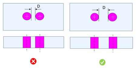
Minimum Spacing Between Insert Holes
Composite structure panels used in aerospace products have a higher strength-to-weight ratio. But due to their weak core structure, they are not suited to withstand localized loads. Hence, inserts are used to transfer such localized loads to composite panels. Maintain enough spacing between insert holes to avoid the overcut problem.
Recommendations:The general guideline suggests that for the honeycomb panel, the minimum spacing should be 30 mm, and for the foam, it should be 20 mm
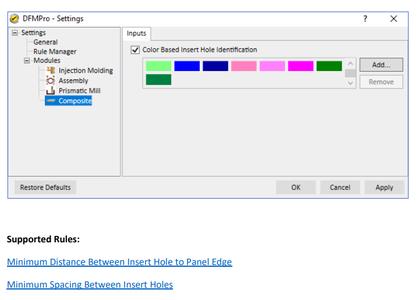
Composite - DFMPro Settings
Insert holes are identified through colors. Users can define colors code to identify Insert Hole or RGB values. It is a Global-level setting, and only the admin can define it
Enhanced Existing Rule
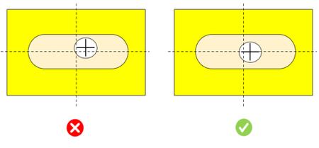
Slot to Hole Alignment - Assembly Module
Gap between two Parts: Distance between faces of parts on which hole and slot are present.
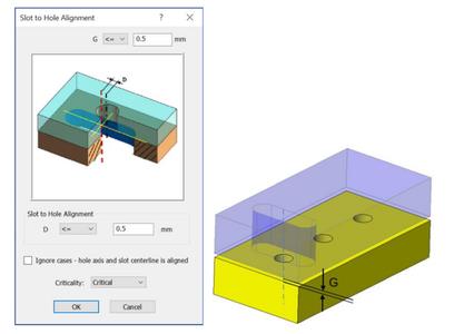
Selection of"Ignore cases - hole axis and slot centerline is aligned"checkbox allows to ignore cases where the hole axis and slot centerline is aligned.
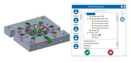
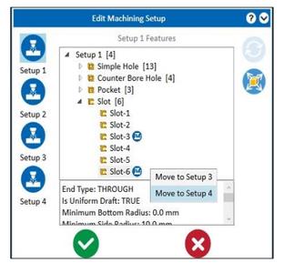
Added New Feature - Machining Setup (Mill Module)
Machining Setup
It provides an option to view and edit machining setups. Machining setups and their associated feature information would further help the design engineer optimize the design. Machining features are classified into different setups, and the design engineer can view setups with machining direction. With the button, features can be moved from one setup to other valid setups.
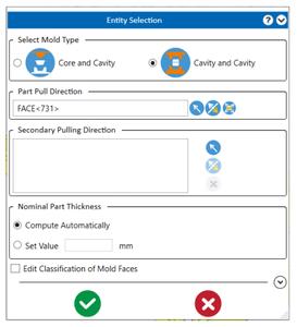
Cavity and Cavity Mold Type support
DFMPro provides an option to select mold type Core/Cavity and Cavity Cavity. Depending on mold type selection and pulling direction, mold faces are classified into two half - Cavity 1 and Cavity 2.
DFMPro is a CAD integrated solutiondeveloped using HCL's DFx technology to carry out DFx review of product design. DFMPro enables faster, less costly and more optimized product development, as well as automation of the DFx review process. DFMPro provides a sophisticated environment for designers to custom-configure the pre-built design rules and hence the knowledge. Providing simple, accurate and robust design analysis based on DFx related rules, DFMPro ultimately leads to better products by giving designers the confidence and capabilities to build superior models. Designers are free to innovate with the assurance that they won't pass costly mistakes downstream.
A: DFMPro is available as add-in on top of Dassault SolidWorks, Siemens NX and PTC Creo Parametric. It is also available as a standalone version named as 'Geometric DFX' which supports file formats from all leading CAD platforms including CATIA, Solid Edge and Inventor.
DFMPro for NX, a best practice driven design for manufacturing software integrated within NX, help design engineers to identify and evaluate their designs for downstream manufacturability, assembly, quality, serviceability, (DFx) related issues upfront and reduce unnecessary rework and engineering changes. It uses the existing, familiar and proven NX Check-Mate framework, and provides an HD3D interface for problem navigation and tagging. It facilitates out-of-the-box validation for manufacturing process like plastic injection molding, sheet metal fabrication, machining, casting, assembly and more
DFMPro For NX Overview
HCL Technologiesis a next-generation global technology company that helps enterprises reimagine their businesses for the digital age. Our technology products, services and engineering are built on four decades of innovation, with a world-renowned management philosophy, a strong culture of invention and risk-taking, and a relentless focus on customer relationships.
Product:Geometric DFMPro
Version:9.0.0 build 2301
Supported Architectures:x64
Website Home Page :
https://dfmpro.com/Languages Supported:english
System Requirements:PC *
Size:287.5 mb
Buy Premium From My Links Hot4share To Get Resumable Support and Max Speed
DOWNLOAD FROM HOT4SHARE.COM
Download ( Rapidgator )
DOWNLOAD FROM RAPIDGATOR.NET
Download (Uploadgig)
DOWNLOAD FROM UPLOADGIG.COM
Download ( NitroFlare )
DOWNLOAD FROM NITROFLARE.COM